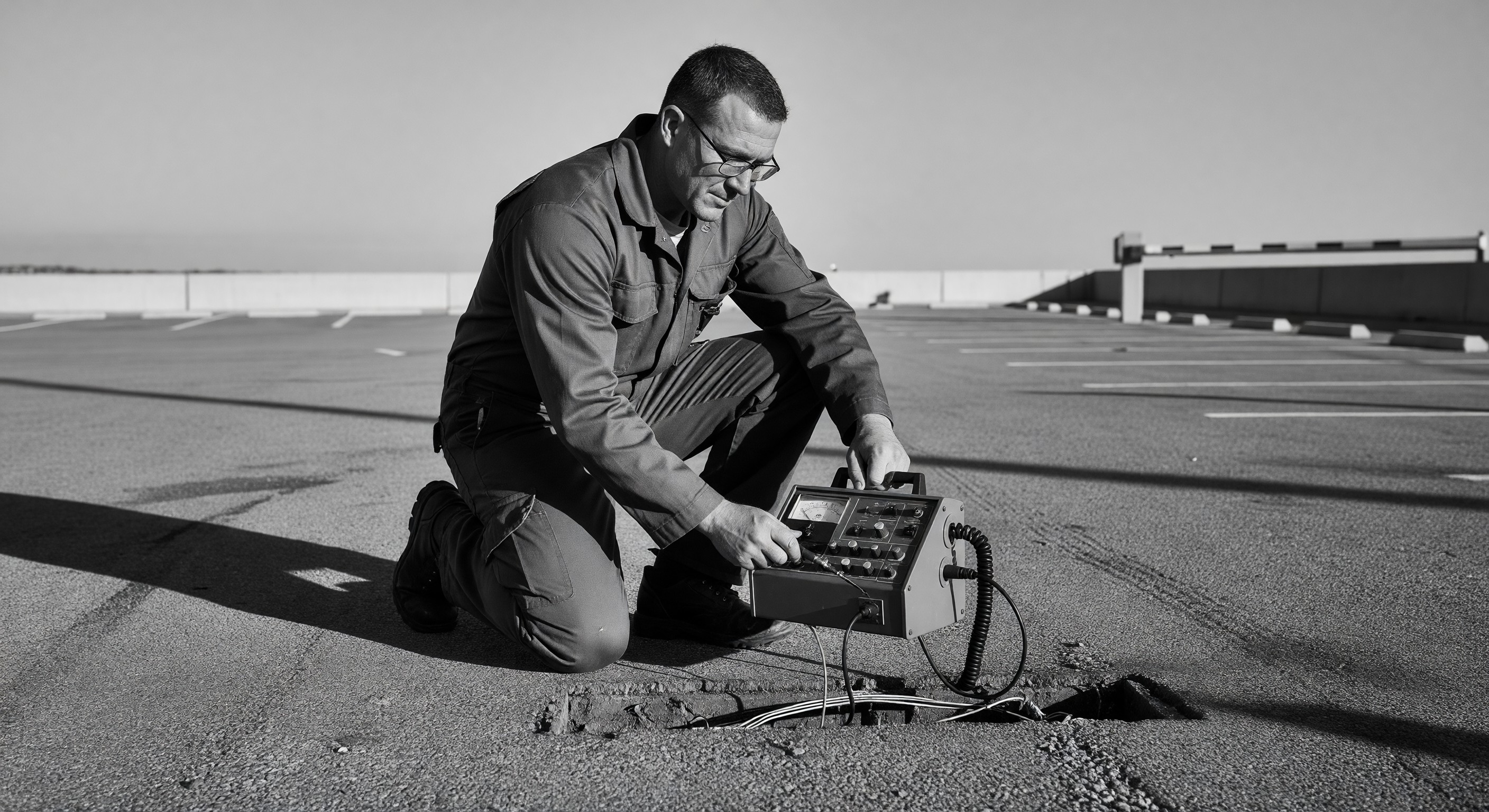
Inductive loop detectors are the most common vehicle-sensing technology deployed at parking barrier gate installations across North America. They are also one of the most frequent sources of nuisance faults, gate hesitation, and complete lane outages. A technician who understands the physics of the system and follows a disciplined diagnostic sequence can resolve the majority of field failures without returning to the shop for additional parts. This guide covers the full diagnostic workflow—from visual inspection through bench-level inductance measurement—for technicians servicing any make or model of loop detector or parking barrier gate.
Loop Detector Fundamentals
An inductive loop detector operates on a straightforward electromagnetic principle. A wire loop—typically 14 to 16 AWG crosslinked polyethylene (XLPE) or direct-burial twisted pair—is embedded in a saw-cut slot in the pavement. The loop is connected to a detector module that drives the loop at a resonant frequency, commonly between 10 kHz and 200 kHz depending on manufacturer and sensitivity setting. When a ferrous vehicle enters the detection zone, the metal mass changes the inductance of the loop. The detector electronics measure this frequency shift. When the shift exceeds a programmed threshold, the detector triggers an output relay, signaling the gate controller to open.
The critical parameters for any loop are:
- Inductance (L): Measured in microhenries (µH). Typical installed loop inductance ranges from 50 µH to 700 µH. The detector module must be tuned to match the installed loop.
- Q-factor (Quality factor): A ratio of inductive reactance to resistance. Higher Q means better sensitivity. Low Q—caused by resistive losses, corroded splices, or poor wire quality—degrades detection reliability.
- Lead-in length: The twisted pair running from the loop edge to the detector panel. Excess untwisted lead-in adds unwanted inductance and antenna surface area for electrical noise pickup.
Manufacturers including Reno A&E, Diablo Controls, OSCO, and Eberle design their modules around these fundamentals. BEA manufactures active microwave and passive infrared alternatives, but their loop-compatible products still rely on the same inductance-shift principle when wired to a traditional loop. Understanding the physics makes the diagnostic steps logical rather than procedural.
Common Failure Modes
Field experience at parking facilities points to four recurring causes of loop detector failure.
Saw-cut damage during installation or repaving. The pavement slot cut for the loop wire must be wide enough to accept the wire without pinching and deep enough—typically 2 to 3 inches—to protect it from surface load stress. When the cut is too shallow, repeated vehicle compression cracks the wire insulation. Hairline insulation breaks create intermittent ground faults that appear as erratic sensitivity or false detections, particularly in wet weather. A loop that tests clean on a dry summer day may fault constantly after rain.
Sealant degradation. The loop slot is filled with sealant—hot-applied rubberized crack filler, polyurethane, or epoxy—to hold the wire in position and exclude moisture. UV exposure, thermal cycling, and traffic wear cause sealant to shrink, crack, and debond. Once the sealant fails, water infiltrates the slot, freeze-thaw cycles accelerate wire movement, and abrasion from grit completes the insulation damage. Sealant failure is the single most common upstream cause of loop deterioration at northern facilities.
Wire break or open circuit. Complete wire breaks—usually at the saw-cut corners where the wire bends 90 degrees, or at the splice junction box—produce a definitive open-circuit fault. Most detector modules will display a fault LED or output a fault relay when inductance drops below the detectable range. Unlike intermittent faults, open circuits are among the easiest to confirm with a multimeter.
Lightning and electrical surge. Loop wire acts as a ground-coupled antenna. A nearby lightning strike induces a voltage spike through the loop that can destroy the detector module input stage. Facilities without surge arrestors on the loop leads are vulnerable. After a storm, if multiple detector channels in the same panel fail simultaneously, suspect surge damage to the modules rather than to the loops themselves.
Field Diagnostic Sequence
A structured sequence prevents chasing symptoms and avoids replacing components unnecessarily.
Step 1 — Visual inspection. Walk the entire loop perimeter at pavement level. Look for cracked or missing sealant, visible wire exposure, pavement heave, and any evidence of saw-cut edges chipping into the slot. Check the junction box for water intrusion, corrosion on terminals, and condition of the lead-in terminations. Inspect the detector module for blown fuse indicators, fault LEDs, and signs of heat damage or physical impact.
Step 2 — Multimeter resistance check. Disconnect the loop leads from the detector module. With a digital multimeter set to resistance (Ohms), measure across the two loop terminals. A healthy loop typically reads below 10 Ω—often 1 to 5 Ω depending on loop size and wire gauge. A reading above 10 Ω suggests resistive degradation from corroded splices or damaged wire. An open circuit (OL or infinite resistance) confirms a wire break. Then measure from each loop terminal to earth ground. Any reading below 1 MΩ indicates insulation damage—a ground fault that will destabilize the detector and cause false triggers.
Step 3 — Inductance measurement. A basic multimeter cannot measure inductance. Use a handheld LCR meter or inductance bridge. Reconnect across the loop terminals and measure inductance in microhenries. Compare the reading to the detector module’s specified operating range, which is printed on the module label or available in the manufacturer’s installation guide. Most modules accept loops between 50 µH and 1,000 µH. A reading significantly outside that range—or a reading inconsistent with historical values if documented at installation—indicates physical changes to the loop geometry, possibly from pavement repair work cutting or shifting the wire.
Step 4 — Module substitution. If the loop measures within spec but the detection behavior is still incorrect, swap the detector module with a known-good unit of the same model and sensitivity range. If behavior normalizes, the original module has failed internally. Document which channel failed and whether a surge protector was absent—this informs the repair, not just the replacement.
For a broader treatment of barrier gate fault diagnosis beyond the loop circuit, see the site’s troubleshooting barrier gate problems guide.
Frequency Crosstalk Between Adjacent Lanes
Multi-lane parking entries and exits create a condition called crosstalk or loop coupling. When two loops operate at the same or closely adjacent frequencies, the magnetic fields interact. One loop can induce a false frequency shift in the neighboring loop, causing phantom detections—the gate opening when no vehicle is present—or mutual suppression, where neither loop reliably detects vehicles.
The solution is frequency separation. Quality detector modules offer frequency selection switches or jumper settings labeled with letters or numbers (typically A through D, or 1 through 8) corresponding to different operating frequencies. Adjacent loops must be set to different frequency bands. The minimum recommended frequency separation depends on the manufacturer, but as a general rule, no two loops within 10 feet of each other should share the same frequency setting.
When installing or diagnosing multi-lane facilities, document the frequency setting of every loop in the lane layout. Technicians who inherit an undocumented installation should cycle through all available frequency settings on one module at a time while monitoring adjacent lanes for symptom changes. This systematic approach identifies problematic frequency pairings without guesswork.
Twisted lead-in wire also reduces crosstalk susceptibility. Untwisted lead-in acts as an inductive antenna. Manufacturers including Reno A&E specify a minimum twist rate—commonly 3 to 6 twists per foot—for the lead-in pair from the loop edge to the detector panel. Inspect lead-in twist integrity at the junction box, where the twist is often loosened during field terminations.
Weather and Temperature Effects
Temperature and moisture affect loop detector performance in predictable ways that inform seasonal diagnostics.
Cold weather: Pavement contraction in freezing temperatures slightly reduces saw-cut slot width. This can pinch the wire, increasing resistance and lowering Q-factor. At the same time, the detector module itself operates more slowly at extreme cold. Technicians servicing gates in northern climates should verify detector sensitivity settings are not at minimum during winter months.
Freeze-thaw cycling: Water that infiltrates a degraded saw-cut slot expands when it freezes, mechanically stressing the wire insulation. This process repeats hundreds of times over a northern winter, progressively damaging the wire at the same stress points—corners and splice locations. Facilities that report loop problems emerging in spring are almost always dealing with freeze-thaw damage that accumulated over winter.
Wet weather and ground faults: As noted under failure modes, intermittent ground faults often appear only when the loop is wet. A loop that fails rain tests but passes dry-condition testing has an insulation breach. The moisture creates a conductive path between the loop wire and the surrounding reinforced concrete or steel rebar, which effectively short-circuits the loop inductance to ground. This produces instability—the detector oscillates between triggered and released states, or refuses to tune at all.
High summer temperatures: Hot pavement softens asphalt, allowing the saw-cut slot to close slightly and pinch wires. Hot-applied sealant can flow out of the slot if it was applied at too low a melting point for the climate. In high-UV environments, UV-stabilized sealant compounds are required to prevent surface chalking and cracking within the first two seasons.
When to Repair vs Replace
The repair-versus-replace decision depends on the failure mode, the age and condition of the existing installation, and the cost differential between patching and full loop replacement.
Repair is appropriate when:
- The failure is isolated to the splice junction box (corroded terminals, loose connections)
- The detector module has failed but the loop itself measures within spec
- The sealant is degraded at the surface but the loop wire shows no resistance or insulation fault
Replace the loop when:
- The loop shows an insulation-to-ground fault below 100 kΩ, indicating significant wire jacket damage
- Resistance exceeds acceptable limits and no splice repair restores it
- The loop is more than 10 to 15 years old in a high-traffic lane with a history of repairs
- The saw-cut itself was made incorrectly at installation (corners not rounded, depth inconsistent) and has required multiple repairs
Full loop replacement requires saw-cutting new slots or reopening existing ones, threading new wire, installing a new junction box and lead-in, and resealing. In most cases, the pavement disruption cost exceeds the material cost. Plan loop replacements during scheduled pavement maintenance cycles to reduce mobilization expense.
The barrier gate maintenance preventive schedule includes recommended inspection intervals for loop wire continuity, sealant condition, and module calibration checks that extend loop service life when followed consistently.
Preventing Future Failures
Installation quality determines the service life of any inductive loop. Technicians who cut corners at installation create diagnostic problems for the next three to fifteen years.
Saw-cut geometry. Slots should be cut with a diamond blade to a consistent depth of 2.5 to 3 inches. Corners must be relieved—either with a round corner saw-cut or by installing a 45-degree diagonal cut at each corner—to prevent wire stress concentration at 90-degree bends. The slot width should match the wire diameter plus 20 percent minimum clearance.
Wire selection and routing. Use continuous wire for each loop with no splices inside the pavement. All splices must occur above grade in a sealed junction box. Lead-in wire must be twisted at a minimum of 4 twists per foot from the loop edge to the panel. Excess lead-in should be coiled and stored in the junction box, not looped in the pavement.
Sealant selection. Match sealant to climate. For cold climates with freeze-thaw cycling, use a flexible polyurethane or hot-rubberized asphalt compound with a low-temperature flexibility rating below -20°F (-29°C). For hot southern climates, use a compound with a high softening point to resist flow-out during summer pavement temperatures. The Institute of Transportation Engineers (ITE) publishes guidance on pavement loop installation standards that informs sealant and wire specification choices. The International Municipal Signal Association (IMSA) offers loop detector technician certification programs that reinforce correct installation practices.
Surge protection. Install surge arrestors on all loop leads entering the detector panel in any facility with exterior loops exposed to open sky. The Door and Access Systems Manufacturers Association (DASMA) technical bulletins address electrical protection requirements for gate operator installations, including loop circuits.
Documentation at installation. Record loop inductance measurements, frequency settings, wire gauge, loop dimensions, and lead-in length for every lane at installation. This baseline data dramatically reduces diagnostic time during future service calls and makes module replacement faster and more accurate.
Further Reading
Inductive loop diagnostics intersect with the broader problem of barrier gate fault isolation. If the loop circuit tests clean but gate behavior remains abnormal, the fault likely lies in the gate controller, the wiring between the detector module output and the controller input, or the gate mechanical and electrical systems themselves. The barrier gate installation site assessment guide covers pre-installation evaluation criteria—including pavement suitability for saw-cutting, electrical service requirements, and lane geometry—that directly affect long-term loop reliability.
For technicians who service multiple brands and models, maintaining a calibrated LCR meter, a dedicated loop diagnostic kit, and a written log of baseline inductance values across all managed sites is the single most effective investment for reducing loop-related callback rates. Most recurring loop problems are predictable failures of known degradation pathways—sealant, insulation, and splice corrosion—that a consistent inspection protocol catches before they become gate outages.
Hero image: “Handicap Parking Spaces at SJSU Lot 4, San Jose, California” by Will Buckner, CC BY 2.0, via Wikimedia Commons (https://commons.wikimedia.org/wiki/File:Handicap_Parking_Spaces_at_SJSU_Lot_4,_San_Jose,_California_(45836635652).jpg).

.jpg))