Spring and early summer is when most facility managers schedule barrier gate installations — construction windows align with fiscal budgets, parking demand patterns shift, and project timelines look manageable before fall. What doesn’t get scheduled early enough is the site assessment. Crews arrive to find inadequate conduit runs, unlocated utilities, or a concrete pad that hasn’t cured. The installation stalls. The window closes. Most of these delays trace back to gaps in the pre-installation walkthrough that should have happened weeks earlier.
A thorough site assessment isn’t a preliminary formality — it’s the specification document that determines whether the installation goes cleanly or accumulates costly change orders.
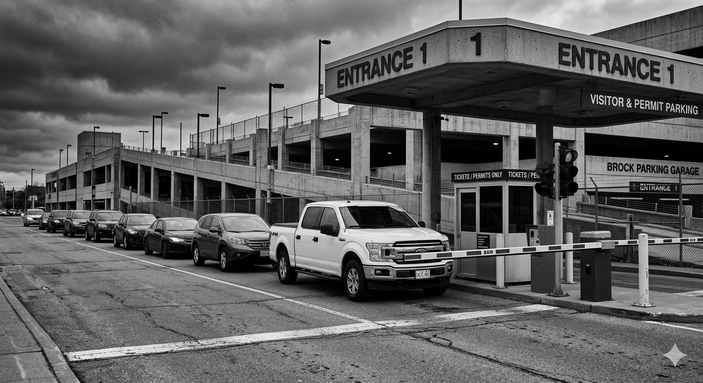
Surface and Foundation Conditions
The barrier gate cabinet must sit on a level, solid, reinforced concrete foundation. Industry installation standards typically call for a pad at least 12 inches thick, poured and fully cured before equipment is mounted. Concrete cure time runs 48 to 72 hours at minimum under normal summer temperatures, but that window extends if crews pour in high heat or low humidity conditions. Schedule foundation work as the first step, not a concurrent one.
Asphalt Condition and Pavement Age
Examine the approach pavement on both sides of the gate location. Cracked, heaved, or patch-repaired asphalt creates problems for two reasons: ground loop detectors cut into deteriorating pavement tend to fail earlier as the surrounding material continues to shift, and uneven surfaces affect how drivers position vehicles relative to ticket dispensers or card readers. If the pavement needs resurfacing, it should happen before loop installation — not after.
Drainage and Grade
Check whether water pools at or near the proposed cabinet location. Barrier gate cabinets sit low to the ground and often share a slab with ticket dispensers or intercoms. Standing water accelerates corrosion on cabinet enclosures and creates ice hazards in shoulder seasons. Confirm that the site grades away from the installation zone or that drainage infrastructure exists to manage runoff.
Underground Utilities and Conduit Routing
Utility conflicts are the single most common cause of installation delays. Before any ground is broken, obtain current utility locates for the full installation zone — not just the cabinet footprint. This includes electrical, telecom, water, gas, and irrigation lines. Many parking lots have irrigation conduit that isn’t captured on facility drawings.
Electrical Service Requirements
Barrier gate operators require a dedicated electrical circuit. Confirm with the equipment specifications whether the system runs on 115V or 230V, and trace the available panel capacity at the nearest distribution point. The conduit run between the panel and the cabinet location determines both cost and timeline. Runs exceeding 50 feet may require wire gauge upgrades to compensate for voltage drop.
Use non-metallic conduit wherever runs pass through or under the pavement. Metallic conduit near a ground loop detector introduces eddy currents that distort the inductive field and cause detection errors — the gate fails to recognize vehicles reliably, or triggers without cause.
Ground Loop Detector Placement
Loop detectors embedded in the pavement are how most barrier gate systems detect vehicle presence for entry, exit, and anti-trap protection. The standard loop dimensions are approximately 6 feet by 6 feet, cut 2 to 2.5 inches deep into the pavement surface. Lead wires from each loop run to the gate controller cabinet through protective conduit — never unprotected across open pavement.
If the design calls for multiple loops (entry detect, exit detect, anti-trap), space them a minimum of 4 feet apart to prevent signal interference between adjacent loops. Mark all loop locations on the site plan before any cutting begins, and verify that planned loop positions don’t intersect with utility lines below.
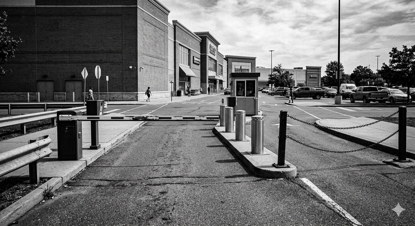
Traffic Flow and Clearance Geometry
A gate that works mechanically but disrupts traffic flow creates operational problems from day one. The site assessment must document lane width, queuing depth, boom arm clearance, and the relationship between entry and exit lanes.
Lane Width and Boom Arm Length
Measure the actual paved lane width, not the designed lane width. Many older parking facilities have lane widths that vary due to curb repairs, paint drift, or informal equipment placement. Boom arms are available in lengths from 10 to 20 feet — selecting the wrong length means the arm either doesn’t clear the lane or extends past the curb into adjacent traffic. The boom tip should clear the widest expected vehicle with a margin of at least 12 to 18 inches on each side.
Queuing Distance
Measure the distance between the gate cabinet position and the nearest point where queued vehicles would block a public street, fire lane, or primary drive aisle. Most jurisdictions require a minimum stacking distance before the gate — commonly three to five vehicle lengths — to prevent vehicles from backing into traffic. If the site can’t accommodate that queue, the gate location may need to move, or the access design may require a reconfigured entry sequence.
Pedestrian Pathways
Identify where pedestrians cross the vehicle lane near the gate location. Barrier gates are a pinch point risk for pedestrians who walk close to vehicle lanes, and many jurisdictions have specific requirements for signage, safety edges, and detection coverage in mixed-use access zones. The site assessment should document any crosswalks, sidewalk connections, or pedestrian routes within 30 feet of the gate.
Integration Points and Communication Infrastructure
Modern barrier gate systems don’t operate as standalone hardware. They connect to access control platforms, intercom systems, payment terminals, license plate recognition cameras, and — increasingly — cloud management dashboards. Each integration point requires its own conduit run, power supply, and mounting surface.
Camera and LPR Mounting
If the installation includes license plate recognition, camera position relative to vehicle approach angle is critical. Cameras mounted too high or at the wrong lateral offset produce images that LPR software can’t read consistently. The assessment should identify mounting surfaces (existing structures, dedicated posts, or wall brackets), confirm sightlines are clear of obstructions, and note any ambient lighting conditions that could affect nighttime image capture.
Network and Communication Access
Confirm whether the installation site has access to the facility’s network infrastructure or requires cellular connectivity as the primary communication path. Note conduit routing from the gate cabinet to the nearest network closet or access point. Cloud-connected systems require reliable uptime — a site that depends on a long, unprotected conduit run through a high-traffic area is a maintenance liability.
Permitting and Scheduling Dependencies
Permitting timelines are compressing in many municipalities as construction volumes remain elevated. In some jurisdictions, permit processing times for commercial electrical and construction work have increased significantly in recent years — meaning applications submitted in May may not clear until late summer if submitted without lead time. Identify which permits the installation requires (electrical, building, right-of-way if conduit crosses public property) and submit early.
Coordinate the installation sequence so foundation concrete, pavement cutting, conduit installation, and equipment mounting don’t stack into a single week. Trades working in sequence — rather than simultaneously — reduces errors, rework, and site access conflicts.
The site assessment is the document that drives that sequence. Facilities that complete it thoroughly before the first permit application tend to receive equipment, complete installation, and begin operation without interruption. Those that skip it tend to find the hard constraints later, when they’re more expensive to resolve.